Products & Data Sheets
Download data sheets here:
Modular Control System Data Sheet.pdf
SW64DR Data Sheet 20230501.pdf
SW64GP Data Sheet 20230501.pdf
Product Index
Standard
Off-the-shelf boards
MSC03
- Modular System Controller Board
*** NEW PRODUCT ***
SW64
-
Switch
Driver and I/O Boards
*** NEW PRODUCTS ***
I2C01
- I2C Module
GTT50P
- Touchscreen Displays
Custom I/O Boards
SW72
- 72 Channel Switch Driver Board
SW40x13
- 40 Position Switch Driver Board
SW26x20
- 26 Position Switch Driver
Board
KL01
- Relay Board
BKPS01
- I/O Board
Prototype I/O
Boards
AD9910
- AD9910 Eval Board Breadboard
AD9959
- AD9959 Eval Board Breadboard
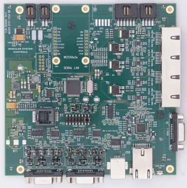
Modular System Control Board *** NEW PRODUCT ***
The Modular System MSC03 Control Board pictured above is the heart of the
system. The MSC03 is the latest
version of the controller board, it supercedes the MSC01 and MSC02,
increases the 5V power available to the I2Cboards
from 1A to 2A and added a general purpose interface for system
monitor functions. It is a small 5.5” x
5.5” board designed to stack with other interface boards.
The board contains the main
control processor, Ethernet, USB and RS232, RS422 & RS485 serial
interfaces, and connectors for the optional modules, power regulators
and 3 I2C busses with 5V power for the I2C01 modules,
I/O boards and the touchscreen display.
This board is powered from the system power supply (9 to 35 VDC) and
can supply up to 2 A of 5V power to the display and I/O boards.
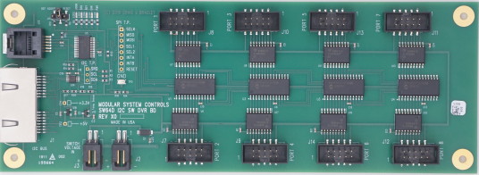
SW64 Series Switch
Driver Boards
*** NEW PRODUCTS ***
The SW64D board pictured above is one of 3 new small 3” x 8.3” boards which
connect directly to the MSC03 controller via the I2C
bus. The SW64D board has 8 8-bit ports with low side drivers
that can directly drive 64 switch coils, relays or
other high voltage high current loads. The SW64DR board is
similar with 4 ports with drivers and 4 TTL I/O ports that can be
used for switch readback or general purpose I/O. The SW64GP
version has 8 ports of TTL general purpose I/O. These boards
contain two I2C RJ-45 connectors, buffers and
a
microcontroller that handles the I2C interface protocol, command
parsing and control for switches, attenuators and parallel I/O. The
micro-controller contains EEPROM non-volatile memory which is used
to store configuration data and contact closure counts. The
boards
also have a voltage regulator to provide 3.3V logic power from the 5V
power supplied by the I2C bus cable. Eval boards are now
available!
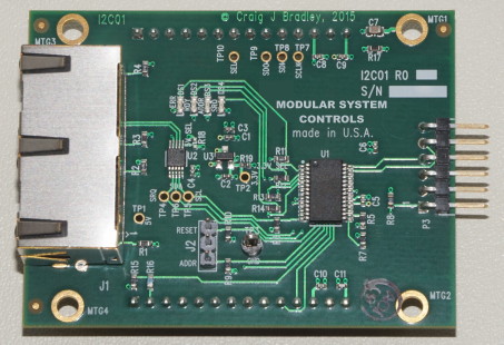
I2C Module
The I2C01 Module pictured above is a small
business card size 2” x 2.65” daughter board which plugs onto an I/O
board with standard 0.1” center header pins. The module
contains two I2C RJ-45 connectors, buffers and the
microcontroller which handles the I2C interface protocol, command
parsing and control for switches, attenuators and parallel I/O. The
micro-controller contains EEPROM non-volatile memory which is used
to store configuration data and contact closure counts. The module
also has a voltage regulator to provide 3.3V logic power from the 5V
power supplied by the I2C bus cable.
GTT50P / GTT70P
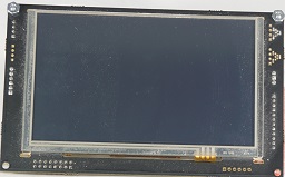
5 Inch & 7 Inch Touchscreen Display
The GTT50P and GTT70P are a 5 and 7 inch full color touchscreen displays with an integrated piezo speaker for operator feedback. The display is controlled
and powered by the MSC03 Controller Board via the I2C bus cable.
The GTT50P and GTT70P displays are shipped preloaded with all of the
graphics files necessary to the standard MSC03 firmware and an I2C
bus cable. The OEM may purchase the display directly from the
vendor and load the files in house if desired. Please consult
the factory for ordering options.
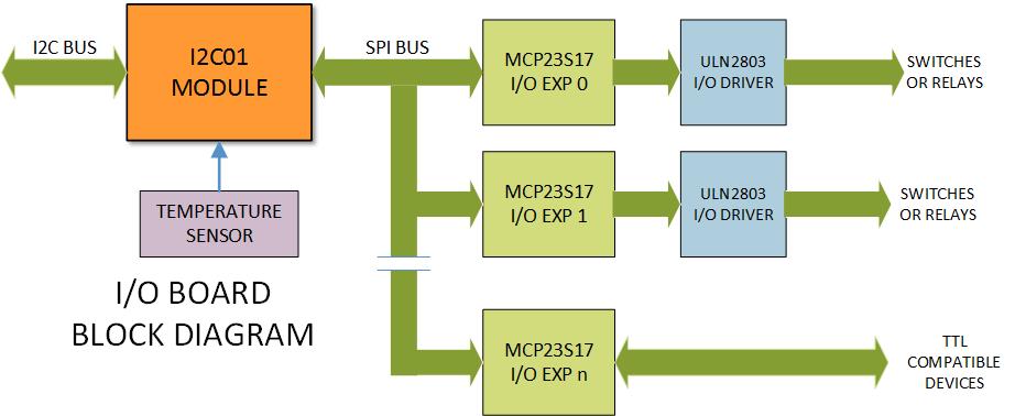
As the microcontroller is on the I2C01 module,
interface boards can be simple 2-sided boards which significantly
reduces the cost. For a
switch driver board, the I/O expanders and any necessary coil driver
circuitry can be placed on the board near the switch connectors to
reduce the length of the traces to the connectors simplifying the
board layout.
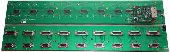
72 Channel Switch Driver Board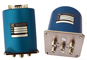
An example 72-channel board is shown above,
which supports nine H3-H6 series 3 to
6-position TTL input switches and nine B
series 2-position TTL input switches from
Charter Engineering, Inc. all with indicator contact
read-back (144 I/O lines). The top board in the picture shows the
component side of the board with the 9 I/O expander chips and the
I2C01 module installed on the right. The bottom board shows the
connectors which plug directly onto the switch assembly eliminating
all switch wiring. The board has two power input connectors (up
right corner of bottom board) to allow daisy chaining of the system
power. Coil voltage and board temperature are monitored and
reported to the system controller.
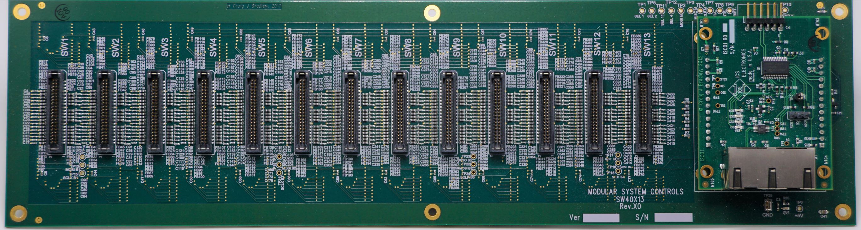
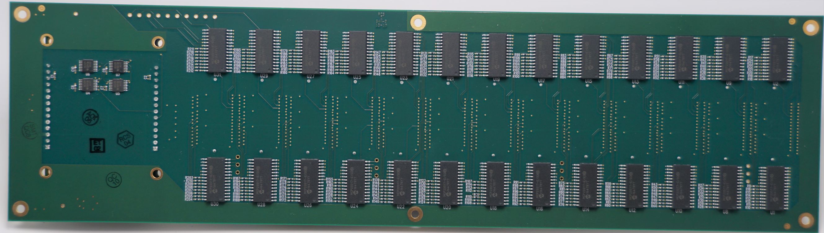
40 Position Switch Driver Board
An example 40-position switch driver board is shown above,
which supports 13 40-position TTL input solid state switches each
switch has 30 control lines for a total of 390 I/O lines. The top
picture shows the
connector side of the board with the switch connectors and the
I2C01 module installed on the right. The bottom picture shows the
component side with the 16-bit I/O expander chips. Voltage and board temperature are monitored and
reported to the system controller.
SW26x20
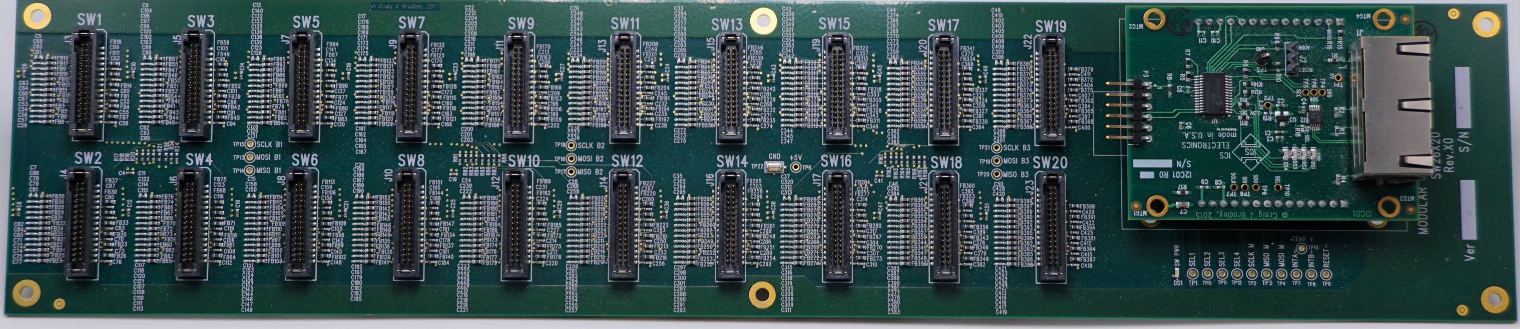
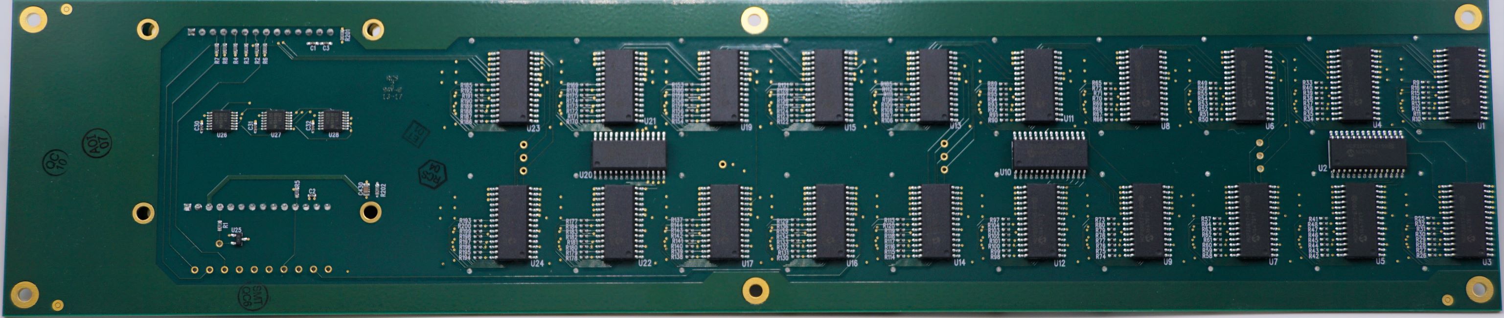
26 Position Switch Driver Board
An example 26-position switch driver board is shown above,
which supports 20 26-position TTL input solid state switches each
switch has 18 control lines for a total of 360 I/O lines. The top
picture shows the
connector side of the board with the switch connectors and the
I2C01 module installed on the right. The bottom picture shows the
component side with the 16-bit I/O expander chips. Voltage and board temperature are monitored and
reported to the system controller.
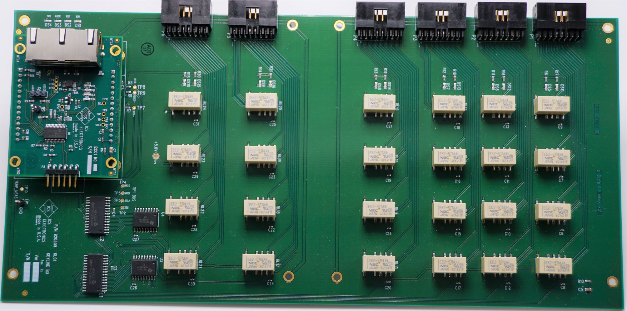
6 Channel
4PDT Relay Board
An example relay board is shown above, which has 24
latching relays connected in 6 groups as 4 pole double throw with
position sensing. The relay positions are monitored for
reliability. Voltage and board temperature are monitored and
reported to the system controller. This board has been used in
radio to antenna switch matrixes to control radio key-lines during
antenna switching. This board is double the size of the MSC02
Controller Board to allow stacking the boards in a chassis.
BKPS01
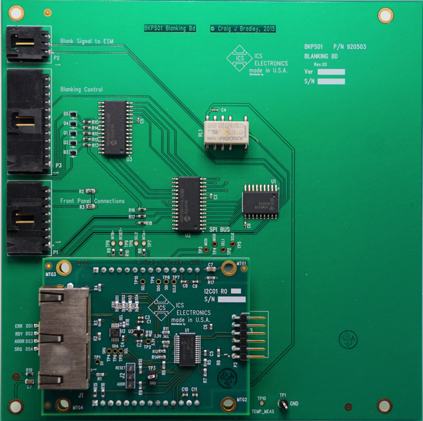
Interface I/O Board
An example interface I/O board is shown above, which has
control inputs, LED drivers and a latching relay. The relay
position is monitored for reliability. Voltage and board temperature are monitored and
reported to the system controller. This board has been used in
radio to antenna switch matrixes to control radio blanking during
transmissions. This board is the same size as the MSC02
Controller Board to allow stacking boards in a chassis.
Due to the fact that the I2C01 module connects to an I/O board with standard header pins on 0.1" centers, custom I/O boards can be easily constructed using standard off-the-shelf breadboards or perforated stock. As the I2C interface and the microcontroller are on the module, the only parts that need to prototyped are the 16-bit I/O expanders and any additional drivers or circuitry needed for the application. Standard ribbon cables can be used to connect additional boards such as evaluation boards in the examples below.
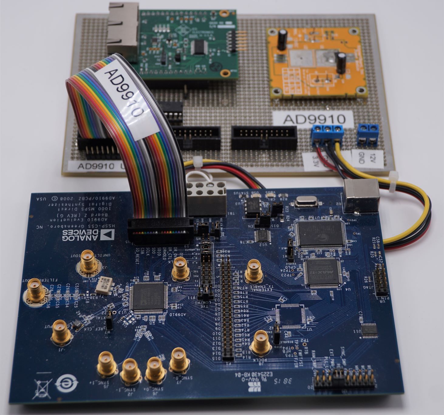
The AD9910 Eval Board is an Analog Devices product with a AD9910 DDS chip on board. A simple breadboard was constructed on perforated stock with one I/O expander and a power supply regulator module. This board was used in a millimeter wave project to provide a sweep ramp. The firmware on the I2C01 module was customized for this project. The distributed processing architecture allows the module to do real time processing while the MSC02 controller board handled an Ethernet interface to a custom Window GUI program.
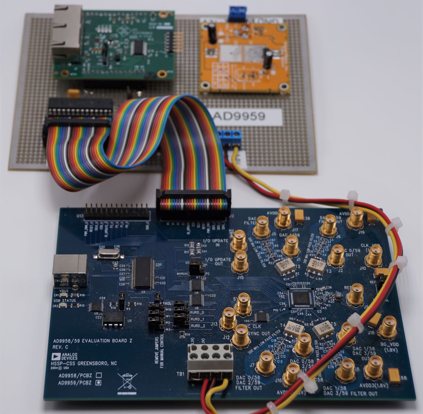
The AD9959 Eval Board is an Analog Devices product with a AD9959 DDS chip on board. A simple breadboard was constructed on perforated stock with one I/O expander and a power supply regulator module. This board was used in a millimeter wave project to provide programmable VCOs. The firmware on the I2C01 module was customized for this project. The distributed processing architecture allows the module to do real time processing while the MSC02 controller board handled an Ethernet interface to a custom Window GUI program.